Factory Acceptance Testing (FAT) for Industrial Control Panels

A control panel’s true performance is determined by how well it operates under actual job-site conditions. Wiring errors, programming mistakes, and incorrect device configuration issues can be unnoticed until equipment is connected.
Finding those problems during startup is expensive. Production schedules are already in motion and every day spent troubleshooting adds cost to the project.
A Factory Acceptance Test (FAT) happens at the panel shop where problems are easier and less expensive to correct. It confirms that the panel matches the approved design and performs as intended before shipment. The process works best when it is planned as part of the Design-Build Approach to Custom Industrial Control Panels, not added after fabrication is complete.
What Is a Factory Acceptance Test?
A Factory Acceptance Test is a structured process used to verify that an industrial control panel meets the project requirements before shipment.
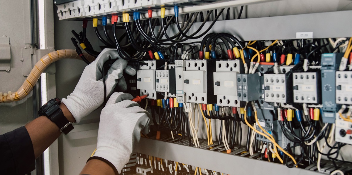
A FAT confirms that the panel will operate correctly before it is shipped. Electrical circuits are verified, PLC programs are tested, HMIs are tested, communications are checked, and protective devices pass checks to operate as intended.
The scope of a FAT varies by project. A simple motor control panel may require only functional verification, while a large Motor Control Panels, operator consoles, and PLC-based systems may require simulated field signals, network testing, drive setup, alarm verification, and customer witness testing.
Define the FAT Scope During Design
The FAT should not begin with a technician deciding what to test after the panel is complete. The project team should identify the test scope, acceptance criteria, required records, and customer participation before fabrication ends. The approved schematics, panel layout, bill of materials, I/O list, PLC program, HMI application, and equipment sequence should be available before testing starts.
AEC’s Custom Control Panel Checklist provides a useful starting point for identifying project requirements before a panel is released for construction. FAT requirements should be added to that planning process so the panel can be built with testing access and simulation needs in mind.
Visual Inspection Comes First
Before any electrical testing takes place, the completed panel should undergo a detailed visual inspection.
This includes verifying that the panel was built according to the approved layout, that components match the bill of materials, and that wiring has been labeled correctly.
This review is easier when the customer understands the purpose of the devices being inspected. AEC’s Motor Control Panel Components Explained article covers the disconnects, contactors, overload relays, VFDs, soft starters, pilot devices, and wiring practices commonly found inside these panels.
A careful visual inspection also provides an opportunity to compare the finished assembly against the engineering drawings before functional testing begins.
Electrical Verification Before Power-Up
Before power is applied, the panel should be checked for continuity, proper grounding, correct control voltage, and secure terminations. Incoming power wiring, branch protection, control transformers, DC power supplies, neutral circuits, and grounding conductors should match the design.
The test should also confirm that installed protective devices are consistent with the documented short-circuit rating. The relationship between fault current, component ratings, and the panel label is covered in Understanding Short Circuit Current Rating (SCCR) on Industrial Control Panels.
Applying power before these checks are complete can damage power supplies, drives, PLC modules, and other components. It can also turn a simple wiring correction into a replacement issue.
Functional Testing Confirms System Operation
Each function specified for the panel should be exercised under controlled conditions.
Typical testing includes:
- PLC program operation
- HMI navigation and screen functionality
- Motor starter operation
- Variable frequency drive configuration
- Alarm functions
- Indicator lights
- Pushbuttons and selector switches
- Safety circuits
- Ethernet or industrial network communications
For PLC-based systems, the FAT should confirm the correct program revision, processor status, scan behavior, and communication with connected devices. The monitoring points discussed in How to Monitor PLC Performance in Real Time are also useful during shop testing and startup.
Simulating Field Devices
Most control panels are tested before they are connected to production equipment.
To accomplish this, technicians simulate the signals that would normally come from field devices.
Digital inputs can be activated manually. Analog signals may be generated using test equipment. Communication devices can often be emulated through software or temporary hardware.
Simulation allows engineers to verify control logic without waiting for installation at the customer’s facility.
Industrial Network and Communications Testing
Modern panels often exchange data with VFDs, remote I/O, HMIs, SCADA systems, managed switches, and other controllers. Device names, IP addresses, subnet settings, communication protocols, and data mappings should be verified before shipment.
Small network mistakes can consume hours during field startup, especially when several vendors are involved. The design considerations in Industrial Network Switch Strategy for PLC Networks provide context for switch selection, network growth, diagnostics, and reliability.
Documentation Is Part of the Deliverable
Successful Factory Acceptance Testing produces more than a working panel.
It should also produce complete project documentation.
This often includes updated electrical drawings, PLC and HMI software backups, bills of materials, test records, configuration files, and any revisions made during fabrication.
If changes were made during testing, those changes should be incorporated into the final documentation before shipment.
Customer Witness Testing
Many industrial projects include a customer witness FAT.
During these sessions, the customer observes testing, reviews documentation, and confirms that the panel satisfies the project requirements before shipment.
FAT does not replace commissioning. It verifies the panel in the shop. The Control Panel Commissioning Checklist for Startup and System Handoff covers the next phase, where field wiring, installed equipment, safety devices, and actual process operation are validated at the site.
Set the FAT Requirements Before the Panel Is Released
A useful FAT has a defined scope, clear acceptance criteria, current drawings, and a record of the results. Discuss those requirements during design and include them in the project schedule. Waiting until the panel is ready to ship usually leads to rushed testing or disagreements about what was supposed to be verified.
AEC designs, builds, programs, and tests custom Automated Control Systems and motor control panels for industrial applications. For a new project, provide the control description, equipment list, electrical requirements, communication needs, and expected FAT participation before fabrication begins.
Related Engineering Resources
Automation Firmware Management Strategy for Industrial Plants
Design-Build Approach to Custom Industrial Control Panels
Custom Control Panel Checklist
Motor Control Panel Components Explained
Understanding Short Circuit Current Rating (SCCR) on Industrial Control Panels
Control Panel Commissioning Checklist for Startup and System Handoff
Industrial Network Switch Strategy for PLC Networks
Svend Svendsen is the principal owner and a certified electrical engineer at Automation Electric & Controls Inc. Svend has decades of panel building experience specializing in custom industrial control systems, motor control panels, operator consoles, automated control systems, and custom control trailers. Automation Electric and Controls Inc. is a licensed ETL 508A panel building shop.