How Panel Design Affects Maintenance and Troubleshooting

A motor stops, the HMI reports a fault, and the maintenance technician has to determine whether the problem is the motor, drive, control circuit, PLC logic, or communication path.
Troubleshooting could take a few minutes or several hours depending on decisions made when the control panel was designed.
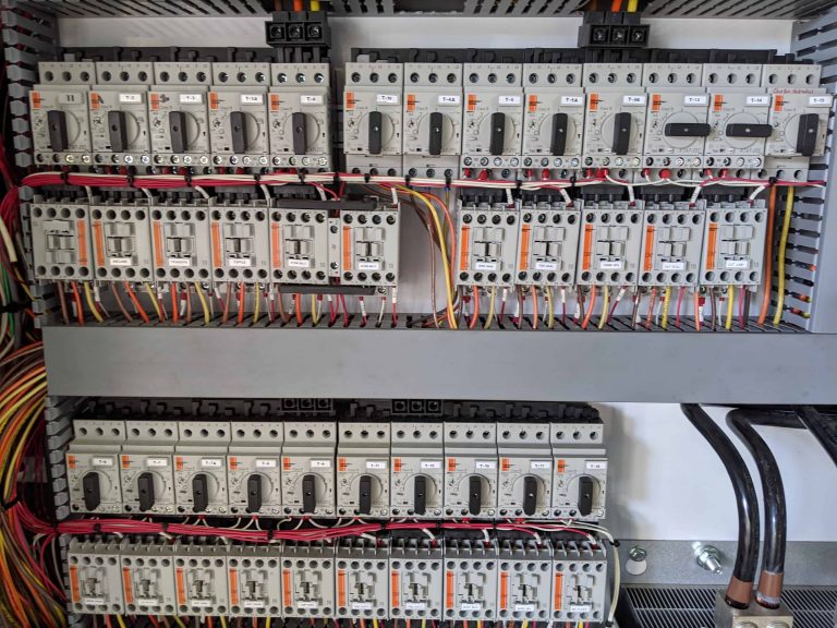
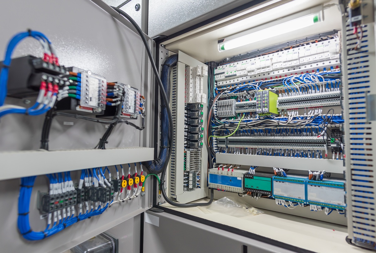
Component placement, terminal layout, labeling, wire routing, power distribution, diagnostics, and documentation all affect how quickly a technician can follow a circuit and isolate a problem. A panel can operate correctly at startup and still be difficult to service.
AEC designs, builds, tests, and services custom industrial control systems. Serviceability is not separate from panel design. It is one of the conditions the finished equipment will eventually have to support.
Plan the Panel Layout for Service Access
A panel can have enough physical space for every component and still be difficult to work on.
Technicians may need access to breaker terminals, PLC modules, removable connectors, VFD keypads, communication ports, fuses, power supplies, relays, and terminal blocks. Some devices also have manufacturer requirements for mounting orientation, spacing, ventilation, conductor routing, and temperature.
The question is whether a technician can inspect, test, disconnect, and replace the component without disturbing unrelated equipment.
That should be evaluated during control panel shop drawing review, while changes are still being made on a drawing instead of inside a completed enclosure.
Organize Power Distribution for Easier Troubleshooting
Troubleshooting often starts by following power.
Is incoming power present? Did a branch protective device operate? Is control voltage available? Is the PLC output energized? Is the starter or VFD receiving the command? Does the field device have power?
The physical panel layout should make those relationships reasonably easy to follow.
AEC’s Power Distribution Inside an Industrial Control Panel explains how incoming power is divided into protected circuits for motor loads, drives, transformers, DC power supplies, PLC equipment, and other devices.
A logical arrangement does not mean every panel has to look the same. A small machine panel and a large multi-motor panel have different requirements. What matters is that the layout reflects the electrical design instead of becoming a collection of components placed wherever space is available.
Put Field Terminals Where Technicians Can Work With Them
Terminal blocks are one of the most frequently used points during installation and troubleshooting.
A technician checking a failed limit switch, pressure sensor, solenoid, motor permissive, or analog signal often needs to work at the terminal strip before going anywhere else.
Field terminals should therefore be easy to identify and reasonably accessible for testing and conductor replacement.
AEC’s Custom Control Panel Checklist already identifies internal layout, labeling, wire routing, and component grouping as considerations when evaluating a new panel. Those same decisions have a direct effect on maintenance after installation.
Labels Need to Match the Installed Equipment
Good labeling is useful only when it matches the drawings.
A technician should be able to identify a device in the enclosure, locate it on the schematic, and follow the associated circuit without guessing which drawing revision is correct.
Field modifications are where this discipline often gets tested.
If a relay is added, an I/O point changes, or a device is replaced with a different configuration, the final documentation should be updated. Otherwise the panel slowly becomes different from the drawings that are supposed to support it.
AEC’s Control Panel Commissioning Checklist includes final drawings, I/O information, network records, PLC backups, and HMI files in system handoff for exactly this reason. Those records continue to matter long after startup.
Isolation and Branch Protection Affect Troubleshooting
A technician needs to know which protective device supplies which part of the system.
Clearly identified branch protection helps narrow the search when a circuit loses power and makes it easier to understand which equipment is affected by a fault.
That does not replace lockout/tagout procedures or the facility’s electrical safety requirements. Panel layout should never be treated as a substitute for safe work practices.
The relationship between the main disconnect, branch protection, motor circuits, control power, drives, and other loads should be visible in both the drawings and the panel.
Component selection affects this as well. AEC’s article on standard versus customer-specified control panel components explains why plant standards, spare-parts inventory, technician familiarity, and programming tools can matter long after the original panel purchase.
Give Technicians Access to the Information Electronic Devices Provide
PLCs, HMIs, VFDs, intelligent overloads, remote I/O, and managed network switches can provide information that helps identify a fault. That information is useful only if maintenance can reach the device and understand what it is reporting.
A drive fault code may point directly to the condition that stopped a motor. PLC status indicators can help distinguish a controller problem from a field problem. Network switch diagnostics may reveal a lost communication link instead of sending a technician down an electrical path that has nothing wrong with it.
The panel layout should provide practical access to those devices without ignoring manufacturer installation requirements.
AEC’s Automation Firmware Management Strategy for Industrial Plants recommends documenting controller, HMI, drive, communication-module, and managed-switch firmware along with the engineering software used with the equipment.
A replacement PLC is much harder to recover when the program exists but no one knows which firmware or software revision it requires.
Diagnostics Should Answer Useful Maintenance Questions
Useful diagnostics help maintenance distinguish between causes.
For example, there is a meaningful difference between the PLC commanding a motor but receiving no run feedback, a permissive preventing the command from being issued, a VFD reporting a fault, and a remote I/O connection being unavailable.
Those conditions may all appear to the operator as “the motor won’t run,” but they require different troubleshooting paths.
HMI messages, PLC logic, drive status, indicator lights, and network diagnostics should be designed to expose useful system state without flooding the operator with information that does not help identify the problem.
This is also where AEC’s field service experience matters. We build the equipment and also service what we manufacture and sell. A panel that can be diagnosed logically is easier to support after it leaves the shop.
Spare Capacity Should Be Usable, Not Just Empty
Leaving unused space inside an enclosure is not the same as designing for future expansion.
Useful spare capacity might include available terminal positions, documented spare PLC I/O, practical wireway capacity, appropriate control-power reserve, or physical space that can actually accept another component while still meeting its installation requirements.
A fixed machine with little chance of modification has different needs than an aggregate or forestry operation when conveyors, sensors, or other equipment may be added later.
AEC’s Designing Industrial Control Panels for Future Expansion addresses that planning in more detail.
The important point for maintenance is documentation. Spare capacity has little value if the next technician cannot identify what is available or whether using it would require changes.
Review the Panel From the Technician’s Perspective
Before fabrication is complete, look at the design as if the equipment has already failed.
Can the incoming and control power paths be followed?
Are the field terminals accessible?
Can the technician identify which breaker supplies a circuit?
Can PLC, HMI, drive, and network information be reached?
Do the labels agree with the drawings?
Those questions add a different perspective to the design review.
AEC’s Factory Acceptance Testing for Industrial Control Panels provides another opportunity to catch labeling, documentation, configuration, and functional problems while the panel is still in the shop.
Automation Electric & Controls custom control systems are fully tested before they reach the field, and its shop services include documentation and labeling intended to make installation, maintenance, and troubleshooting easier.
For an industrial motor control panel, passing the FAT is important. So is making sure the person who opens that panel five years later can understand what they are looking at.
That is the maintenance test a good panel design eventually has to pass.
Related Engineering Resources
- Reviewing Control Panel Shop Drawings Before Production Begins
- Power Distribution Inside an Industrial Control Panel
- Standard vs. Customer-Specified Control Panel Components
- Factory Acceptance Testing for Industrial Control Panels
- Control Panel Commissioning Checklist for Startup and System Handoff
- Automation Firmware Management Strategy for Industrial Plants
- Industrial Network Switch Strategy for PLC Systems
- Designing Control Panels for Extreme Environments
- Industrial Motor Control Panels
Svend Svendsen is the principal owner and a certified electrical engineer at Automation Electric & Controls Inc. Svend has decades of panel building experience specializing in custom industrial control systems, motor control panels, operator consoles, automated control systems, and custom control trailers. Automation Electric and Controls Inc. is a licensed ETL 508A panel building shop.