
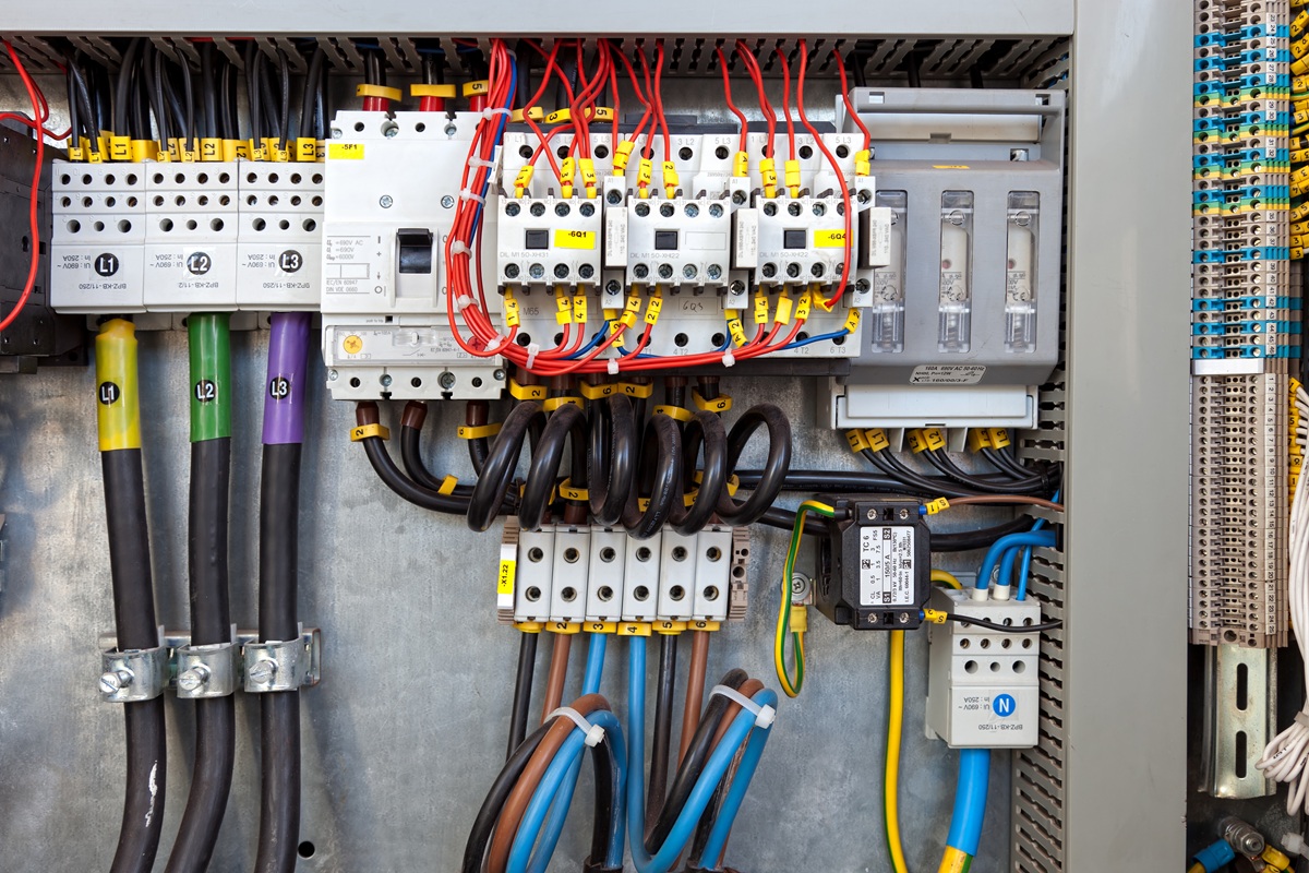
Power Distribution Inside an Industrial Control Panel

Even if a PLC is programmed correctly, the panel can still be difficult to maintain if the power architecture is wrong.
Power distribution inside an industrial control panel is what takes incoming power and distributes it into protected circuits for motors, drives, transformers, power supplies, and other loads. The design makes faults manageable and keeps control power stable.
Power Distribution Starts at the Main Disconnect
The incoming supply establishes the basic architecture of the panel. The main disconnect provides a defined means of isolating the panel, but it is only the beginning of the distribution system.
From that point, power is divided into branch circuits based on the equipment being served. A motor branch may feed an across-the-line starter, soft starter, or VFD. Another branch may feed a control power transformer or DC power supply. Auxiliary circuits may serve heaters, fans, lighting, receptacles, or other panel equipment.
AEC’s Motor Control Panel Components Explained article covers the individual disconnects, starters, overload devices, VFDs, soft starters, and pilot devices commonly found in these systems. Power distribution is the part that ties those devices together into a coordinated electrical design.
Branch Circuits Should Limit the Effect of a Fault
One of the practical goals of branch circuit design is to keep a problem in one part of the system from taking down more equipment than necessary.
For example, a panel controlling several conveyors may have separate protected branches for each motor or drive. If one branch develops a fault, the protection for that branch should operate according to the design instead of forcing maintenance to de-energize unrelated equipment simply to find the problem.
The exact protection method depends on the load and the approved component combinations. Breakers, fuses, motor circuit protectors, overload relays, and drive protection do different jobs.
Control Power Needs Its Own Design
The controls side of the panel usually operates at a different voltage than the main power circuits. A control transformer may step line voltage down for AC control circuits, while a DC power supply commonly serves PLC I/O, sensors, relays, network devices, and operator interfaces.
The power source needs to be sized for the actual connected load, including devices that draw more current during startup or switching. It also needs enough practical reserve for reasonable additions. An undersized supply can create intermittent faults that look like programming or communications problems because the symptoms show up at the PLC or field device rather than at the source.
Control power distribution should also make troubleshooting straightforward. Clearly identified protective devices and terminal points allow a technician to determine whether a problem is on the incoming side, the control supply, or an individual field circuit without tracing the entire panel.
VFD’S and Soft Starters Change the Power Path
Motor starting method changes both the electrical design and the physical layout. An across-the-line starter has a different power path than a soft starter, and a VFD adds power electronics, heat, and configuration requirements.
A VFD should be treated as part of the power system. Input protection, disconnecting means, conductor routing, enclosure temperature, and the motor circuit all have to be considered together. The same is true for soft starters, although their operating characteristics and heat profile are different.
AEC’s VFDs & Soft Starts resource explains where each device fits. The selection should align with the panel architecture because changing the starting method later can affect things like enclosure space, heat load, and wiring.
Grounding, Bonding, and Signal Routing Affect Reliability
Grounding and bonding provide the intended fault path and establish the electrical reference the equipment depends on.
High-current motor conductors and VFD output wiring should not be routed carelessly beside low-level analog signals, encoder wiring, or communications cables. Physical separation, appropriate cable selection, and proper shield termination can prevent noise problems that are difficult to diagnose after startup.
The installation environment can make these decisions more important. Aggregate plants, sawmills, mobile equipment, and other industrial applications add dust, vibration, heat, and long cable runs to the electrical design. AEC’s Designing Control Panels for Extreme Environments article addresses enclosure and environmental issues that have to be considered along with the internal power design.
SCCR Is Part of the Power Architecture
Short Circuit Current Rating should be considered while the power distribution system is being designed, not after the panel is finished. The panel’s overall SCCR depends on the ratings of components in the fault current path and on approved combinations used in the design.
AEC’s Understanding Short Circuit Current Rating (SCCR) on Industrial Control Panels article explains how the rating is determined and why the available fault current at the installation is a key design input.
Panel Layout Should Make the Power System Easy to Service
Power components need enough room for conductor bending, ventilation, replacement, and safe access. Terminal blocks should create a logical transition between internal wiring and field wiring. Wireways need enough capacity to avoid turning future changes into a complete rework of the panel.
These are exactly the issues that should be caught during control panel shop drawing review. Reviewing the power path on the drawings is much less expensive than discovering after fabrication that a disconnect is difficult to reach or a wireway is already full.
Power Distribution Should Support Future Changes Without Hiding Requirements
Spare enclosure space, available distribution capacity, unused terminal positions, and practical control power reserve can simplify later additions. Those decisions still have to be documented so future technicians know what capacity exists and what must be recalculated before adding equipment.
Any change that adds loads or modifies branch circuits can affect conductor sizing, heat, protective devices, and SCCR. Available physical space by itself does not mean a new component can simply be installed.
Verify the Power System Before the Panel Ships
The completed panel should be checked against the approved power design before shipment. Incoming power connections, grounding, control voltage, branch circuits, device configuration, and labeling should all agree with the drawings.
A Factory Acceptance Test (FAT) provides the opportunity to verify electrical construction and functional operation while corrections can still be made in the shop. For custom industrial motor control panels, that testing is particularly useful when the panel contains several motor branches, drives, PLC controls, or networked devices.
What the Panel Builder Needs Before Finalizing Power Distribution
Good power distribution starts with accurate project information. Before the design is finalized, the panel builder should have the actual supply characteristics, motor and load information, available fault current when required, control voltage needs, field device requirements, installation environment, and any known future loads.
AEC designs and builds motor control panels and automated control systems for industrial applications. The best time to work through the internal power distribution is during engineering, while branch protection, control power, layout, and service access can still be adjusted on the drawings.
Related Engineering Resources
- Motor Control Panel Components Explained
- Understanding Short Circuit Current Rating (SCCR) on Industrial Control Panels
- Factory Acceptance Testing (FAT) for Industrial Control Panels
- Designing Control Panels for Extreme Environments
- What Are NEMA Ratings for Electrical Enclosures?
- VFDs & Soft Starts
Svend Svendsen is the principal owner and a certified electrical engineer at Automation Electric & Controls Inc. Svend has decades of panel building experience specializing in custom industrial control systems, motor control panels, operator consoles, automated control systems, and custom control trailers. Automation Electric and Controls Inc. is a licensed ETL 508A panel building shop.


